1 Overview
With the development of new energy, the use of photovoltaic more and more in our lives, and applied to a variety of occasions, the development of photovoltaic elevators from the emergence of the first domestic elevator in 2009 to 2020 KONE elevator company application-oriented platform construction and successful test operation. In this paper, the BLDC motor will be used as the elevator traction machine. The brushless DC motor is different from ordinary motors in that the rotor is a permanent magnet and the stator is a polyphase electrified winding. The motor collects the rotor position feedback signal through the Hall sensor to control the winding of different groups and controls the motor rotation through the PWM square waveform. For its control mode, open loop and double closed loop are generally used for control, but the controllability of open loop control is poor, and the double closed-loop control is widely used and commonly used for controlling speed. Therefore, this paper will adopt the three-closed loop control mode of the servo motor to control the BLDC brushless motor and conduct a simulation analysis.

2 Photovoltaic elevator system
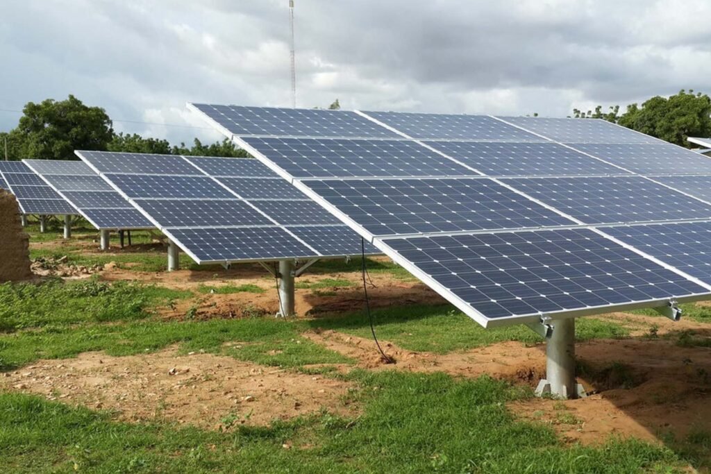
The photovoltaic elevator system framework designed in this paper is shown in Figure 1. The photovoltaic cells are charged and discharged by solar energy and then the energy is stored in the battery. The battery ensures the elevator’s up-down traction operation in the BLDC elevator function, and the system also provides dual power supply modes of solar energy and grid, providing a reliable guarantee for the normal operation of the elevator.
2.1 Photovoltaic power generation
Since the BLDC brushless DC motor only needs direct current to run, the output current of the photovoltaic array can meet its operation and the excess direct current can be stored in the battery, because there is no inverter in the system composition, so the system can only supply power to the DC load. The photovoltaic array uses the MPPT maximum power tracking method to collect solar energy and control the operation of the entire photovoltaic power generation system through the charge and discharge controller. When the battery storage reaches the saturation value, the BLDC elevator is powered by the battery, and in other cases, the AC power of the grid is powered by the direct current output by the inverter transformation.
2.2 PID control of BLDC electrical machine
For the BLDC motor, the most complicated is its control mode. The control of BLDC adopts a DTC controller and motor, but for DTC control, three-closed-loop control is generally adopted. The closed-loop control system is a control system with feedback loops in the output and input of the system, and the output has a negative effect on the control process. The core is to reduce the deviation of the controlled quantity through feedback. PID is widely used in various closed-loop control strategies because of its simple structure. It realizes linear control through proportion, integration, and differentiation. In most cases, it can be used only after discretization, so the discretization formula is as follows: Ki=KpT/Ti is the integral coefficient; Kd=KpTd/T is the differential coefficient, e(k), e(k-1) is the input error at the k and k-1 times, and T is the sampling period. In PID algorithm control, Kp, Ki, and Kd each have a separate coefficient, but it is difficult to determine the size of the three coefficient values in the real use of the scene, so a large number of experiments and search data are needed to determine the appropriate data, so as to achieve accurate and stable control of the motor operation.
2.3 BLDC motor three closed-loop control strategy
The so-called three closed-loop control system is in the speed-current double closed-loop control system with an external position loop, on the basis of controlling the speed and rotation direction of the motor, the rotor position Angle control is added. Generally, rotor speed is controlled by entering a given value or changing the pulse frequency, which can cause the motor to adjust the speed size and direction. The position control system also supports the direct load outer ring to detect the position signal, and the Hall sensor at the motor shaft to detect the motor speed is provided by the detection device at the final load end to provide the position signal. The advantage of this is that it can reduce the error in the intermediate transmission process, enhance the motor speed positioning precision control of the system, and accurately follow the position given. The rotation speed of the position control system is usually changed by the pulse frequency of the external input, and the rotation Angle is determined by the number of pulses in a single time period. BDLC’s three-closed-loop control structure is shown in Figure 2. The system mainly has three regulators, current, speed, and position, and a PWM controller as the reference to realize the control of a brushless DC motor. Now, the three-closed-loop negative feedback PID regulation system is introduced as follows:
(1) The inner ring is the inner current ring, which is completely inside the DTC driver, and detects the output current of each phase of the driver motor through the Hall device, and inputs the negative feedback information to the current regulator, and then adjusts the PID through the PWM control setting, so that the output current is as consistent as possible with the set current. The main function of the current inner ring is to control the motor torque, so generally in torque mode, the smaller the operation value of the driver setting, the shorter the dynamic response time.
(2) In the second ring is the speed ring, by detecting the signal frequency returned by the Hall sensor to calculate the motor speed size so as to carry out negative feedback PID regulation, the PID output in the ring is directly used as the set value of the current ring, so the overall control range of the speed ring includes the speed ring and the current ring.
(3) the third ring is the position ring, the function of the link is to set and mediate the rotor position, and the set value of the speed ring is directly set as the PID output. The feedback signal is determined according to the feedback data of the motor encoder or the final load and needs to be determined according to the actual situation. Since the setting of the speed loop is the output inside the position control loop, in the position control mode, the motor control system carries out three closed-loop calculation processes, and at this time the system needs to carry out the largest amount of calculation, so the dynamic response time is also the most, and the response speed is also the slowest. In general, in the entire operation process, the three modes will use the current ring, and the current ring as the basis for controlling the operation of the motor, in the speed and position control, the control system is actually in the current (torque) control so as to match the speed adjustment and position adjustment to achieve the corresponding control.

3 Analysis of simulation and experimental results
Based on SimuLink modeling on the MATLAB system, the BLDC motor of the photovoltaic elevator is simulated with three closed-loop control systems. In this simulation, the speed of the motor is 1000rad/s, the torque is 5N*m, and the time of the motor from stationary state to stable operation is 0.3s. Set the reverse signal to make the electronic simulation system run in the reverse direction. The simulation results prove that BLDC can be used as a traction machine of the photovoltaic elevator to achieve accurate control of the car’s rising and falling speed and the car’s moving distance. The simulation torque of the motor is shown in FIG. 4, the speed is shown in FIG. 5, and the phase current feedback signal of the Hall sensor is shown in FIG. 6.
4 Conclusions
Through the analysis of the photovoltaic elevator, the control system of solar power generation and BLDC motor is studied, and the three-closed-loop control analysis is carried out for the BLDC motor. The simulation model of three-closed-loop control of current, speed, and torque is built in a Simulink environment, and the positive and negative rotation mode of the motor as an elevator tractor is simulated. The simulation results show that the system exhibits excellent stability and dynamics. The three control modules can adjust the position of the motor stably by rotating speed and direction. The system has almost no overshoot and strong running stability.


