At present, the passivated emitter and rear cell (PERC) technology has become the mainstream efficient technology in the photovoltaic industry to improve the conversion efficiency of crystalline silicon solar cells. PERC technology can passivate the silicon wafer by adding a passivation layer (aluminum oxide or silicon oxide) on the back of the silicon wafer, which can effectively improve the minority carrier life. In order to prevent the passivation layer from being damaged and affect the passivation effect, a silicon nitride layer is also coated outside the passivation layer. The back passivation introduced in PERC technology can reduce the recombination rate of the carrier on the back surface of the battery to less than 50 cm/s, and the surface suspension key to less than 1011 eV • cm2, thus improving the back recombination of the battery and increasing the minority carrier life of the battery. In addition, the back laminated passive film of the PERC monocrystalline silicon solar cell acts as a back reflector, which can reflect more long wavelength light back to the battery, thus improving the long wave response of the battery. However, because the back passivation layer of the PERC monocrystalline silicon solar cell is an insulating layer, it cannot form an electrode path with the aluminum back field. Therefore, it is necessary to slot the back of the silicon chip by laser to form a local back surface field (LBSF) of the PERC monocrystalline silicon solar cell.
At present, laser slotting usually uses a 532 nm laser, which can ablate a part of the silicon nitride layer on the back surface (this process is also called laser slotting process), and then complete the slurry printing on the back of the silicon chip and high-temperature sintering. Because there is no barrier of silicon nitride layer in the laser slotting area, the aluminum slurry can directly penetrate the passivation layer and contact silicon, and form aluminum silicon alloy with silicon substrate under high temperature sintering conditions, thus reducing the series resistance and smoothly deriving the current.
The area of the laser slotting area on the back (that is, the area where the passivation layer is destroyed) has a decisive impact on the passivation effect of the PERC solar cell. Theoretically, the smaller the area of the laser slotting area, the smaller the damage to the passivation layer, the higher the minority carrier life, and the higher the open circuit voltage. But at the same time, the area of the laser slotting area cannot be too small. If the area of the slotting area is too small, the aluminum slurry cannot completely penetrate the laser slotting area in the process of high-temperature sintering, that is, the slotting area cannot be filled, which will form a so-called cavity. Then the cavity area cannot form a good aluminum silicon contact, which will affect the series resistance and the filling factor, and then affect the conversion efficiency of the battery.
At present, there are many reports on the research of laser graphics on the back of PERC monocrystalline silicon solar cells in the industry. Li Jianqi et al. Invented a laser slotting pattern in which the linear slotting area and the line segment slotting area coexist on the back of the battery, and the linear slotting area and the line segment slotting area are intermittently arranged. Yu Dongwang et al. Invented a pattern that combines line segment slotting and point hole slotting, including the corresponding arrangement and dislocation arrangement of point holes and discontinuous line segments. These figures are to retain more passive film area and reduce the damage to the back passive layer; At the same time, it can also improve the problem of large aluminum silicon contact resistance caused by the slotting of the line segment, thus improving the open circuit voltage and short circuit current of the PERC monocrystalline silicon solar cell, and ultimately improving the conversion efficiency of the battery.
In this paper, experimental verification and comparison of the existing laser graphics are carried out to explore the laser parameter settings and laser graphics that can enable the PERC monocrystalline silicon solar cells to obtain the best electrical performance, and the changes in electrical performance are analyzed.
1. Experiment introduction
The raw material used in this experiment is solar grade boron doped p-type diamond wire cut single crystal silicon wafer, which is 156mm in size × 156 mm, 180~200 thick μ m. The resistivity range is 1 ~ 3 Ω• cm.
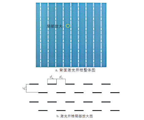
Three experiments were designed: the orthogonal experiment of laser speed and laser solid line ratio, the contrast experiment of different laser slot spacing, and the contrast experiment of back electrode laser hollowing and laser filling. The laser pattern on the back of the PERC monocrystalline silicon solar cell is shown in Figure 1. Where d1 is the distance between two adjacent laser slotting lines; D2 is the laser scanning distance; D3 is the distance of one laser scanning cycle.
In the experiments, the German Halm tester was used to characterize the electrical performance of the battery, and Olympus microscope was used to observe the laser spot scanning morphology of the silicon wafer surface and the change of aluminum paste filling rate on the back of the battery.
2. Experimental results and discussion
2.1 Orthogonal experiment of laser speed and laser solid line ratio
The filling rate of aluminum paste at the laser slotting position on the back of the PERC monocrystalline silicon solar cell will directly affect the conversion efficiency of the battery, while the filling rate of aluminum paste on the back of the battery is jointly controlled by the laser speed and the solid line ratio of the laser spot scanning on the back of the battery (hereinafter referred to as the “laser solid line ratio”). The laser solid line ratio is the ratio of d2 to d3 in Figure 1. The laser speed will cause the distance between laser scanning spots to change, so the difference of laser speed will cause the intersection, tangency and separation between laser spots. The change of laser spot position due to the change of laser speed is shown in Figure 2. The position difference of laser spot will affect the filling of paste printing.
Zhang Jinhua et al studied the matching relationship between the position of laser spot generated by different laser speeds and the ductile corrosion performance of aluminum paste. The results show that: when the ductile corrosion of aluminum paste is strong, the corresponding laser spot positions are separated; When the ductility corrosivity of aluminum paste is weak, the corresponding laser spot positions are intersected; When the ductility corrosivity of aluminum paste is moderate, the corresponding laser spot position is tangent. The contact ratio between aluminum paste and silicon substrate is directly affected by the laser speed and the laser solid line ratio, which affects the contact resistance of PERC monocrystalline silicon solar cells.
Laser speed and laser solid line ratio jointly affect the contact ratio of aluminum paste and silicon substrate. In this paper, orthogonal experiments are used to obtain the change of aluminum paste filling rate at the back of battery under different laser speed and laser solid line ratio.
2.1.1 Experimental design
The laser slotting device uses a nanosecond pulse laser with a wavelength of 532 nm, and the laser scanning device uses a diameter of 35 μ M round spot. As mentioned above, the speed of the laser will affect the distance between laser spots. Because of the speed difference, there may be three states of spot intersection, tangent and separation. Therefore, in this experiment, the laser speed is 14000, 16000, 18000, 20000 and 22000 m/s respectively, and the solid line ratio of the laser spot on the back of the battery is 10%, 30%, 50%, 70% and 90% respectively.
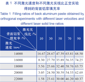
The two parameters, laser speed and laser solid line ratio, were used for orthogonal experiments, with a total of 25 experiments, in which 100 experimental batteries were selected for each experiment. After the laser grooved PERC monocrystalline silicon solar cells have gone through the screen printing and sintering processes, the aluminum paste filling rate of the laser holes on the back of the sintered cells is calculated. According to the statistical results of orthogonal experiments, the filling rate of aluminum paste at the back of the battery can be obtained under different laser speeds and different solid wire ratios.
The filling rate of aluminum paste on the back directly affects the ohmic contact of the battery, thus affecting the filling factor and short-circuit current of the battery. The filling rate of aluminum paste is calculated as the ratio of the number of laser spots filled with aluminum paste at the laser position to the total number of laser spots after printing and sintering at the back laser position.
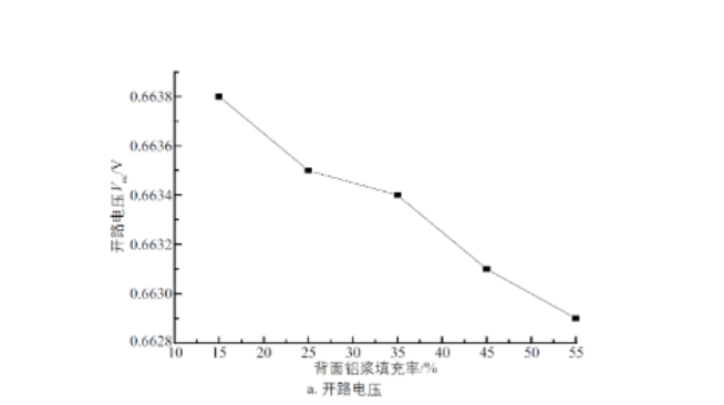
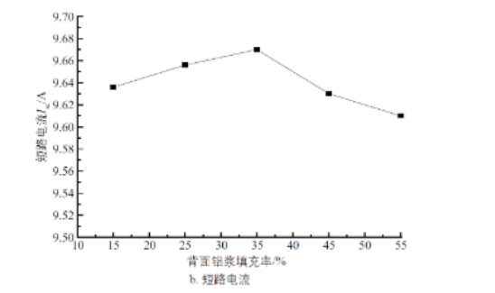
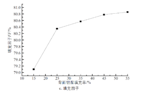
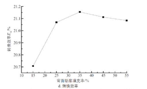
Then, according to the orthogonal experiment results, choose the laser condition settings when the filling rate of aluminum paste on the back is 15%, 25%, 35%, 45% and 55% respectively, that is, the corresponding laser speed and the laser solid line ratio for comparative experiments. For each experiment, select 1000 experimental batteries, a total of 5000 experimental batteries.
In this experiment, except that the filling rate of aluminum paste on the back of the battery is different, the experimental conditions and control standards of other processes are the same.